Lego & POV-Ray on Linux
Some time ago I promised to give some basic instructions on how to create nice images of Lego constructions with POV-Ray on Linux. Now that Christmas is arriving, I finally found some time to convert my own instructions into something that can almost be called a "tutorial" :)
What will you need:
If you use Slackware, you can find packages for all of these on my site and SlackBuilds for all except 3 on www.slackbuilds.org. For many other Linux distributions packages are available in their repositories.
First step - Build something!
If you do not have any LDraw file yet with a Lego creation, then now is the time to make one.
As an example for this tutorial, I built a little penguin, based on the instructions here, with LeoCAD:
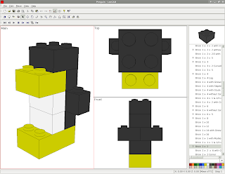
Save your creation with LeoCAD as a ".ldr" file ("File" - "Save as" from the menu). The resulting file in my case was:
Second step - View your model with ldglite or LDView
This step can be skipped, but it is a nice test to check if the programs can find all the LDRAW parts on your computer. LeoCAD uses its own parts library, so being able to view it there does not necessarily mean that the LDRAW library is accessible.
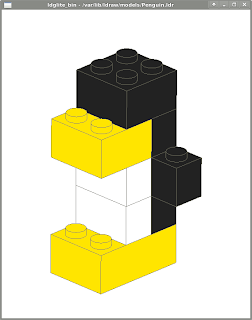
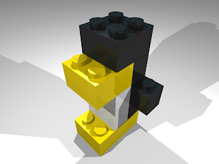
This is how the penguin looks like in ldglite, a simple but very fast program to visualize your creations:
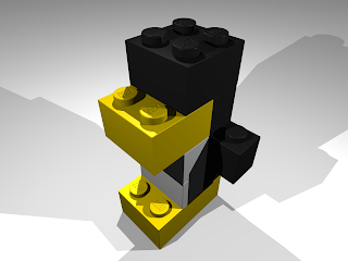
A second option is to use LDView, a very nice and very complete program to visualize your creations. It creates a more realistic view of the model, with some shading effects:

Third step - Ray-Tracing
So the images created by LDView are nice. But we want something even better! Enter POV-Ray, a very professional Ray-Tracing program that is completely free.
It "traces" light-rays, by tracing paths of "light particles" from one or more light sources, bouncing off surfaces and reflecting into the lens of a camera.
So we define the position and colors of the light sources, the position and angle of the camera, the types of surfaces (smooth, reflective, rough, etc.), etc.
Sounds complicated? Well, there is a very nice utility called l3p that tries to do most if it automatically to help us get started. l3p reads an "ldr" file, guesses the best position and angle for the camera so that the whole creation will fit in the image, and sets up three light sources around the model. Then it creates a .pov file that can be read by POV-Ray.
l3p needs to know where the LDRAW library is stored on your computer. This can be set by the LDRAWDIR environment variable like:
Put this in your start-up script like ~/.bash_profile (if you use bash for a shell).
Enough theory, let's create our first .pov file:
This reads the "Penguin.ldr" file we created and writes a "Penguin.pov" file in the current directory.
I used just one option - "-o" - which instructs l3p to overwrite Penguin.pov if it already exists, since we'll perform various tests before we get the final result.
Now let's run POV-Ray to transform the .pov file into an image:
The options here mean:
The result should look like this:
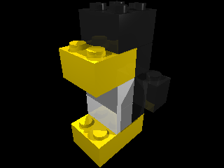
For a first test, it's just about "OK"... But we can do better than this!
Since in most tests we'll run l3p and povray as a sequence, we'll put both commands on one line like this:
The "&&" means that the next command is only executed if the previous terminated without error.
So let's try:
What did we add:
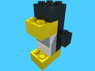
The result should look like this:
Let's improve the image a bit more:
The new options are:
This should be the result:

Advanced options
As I wrote in the beginning, l3p automatically guesses the best position and angle for the camera and light sources. But we can change them as we please.
Let's try something:
I included two new options:
Here is the result:
You can play around with the position of the light sources using the "-lg" option. I'll leave this as an exercise! :)
There are many more advanced options to try. Type "l3p" without any options to see the complete list! If you have a good tip, feel free to post a comment so that I can learn something new.
Using the lgeo library
The images we created with the standard l3p + povray combination look quite good, but when we enlarge the images, the pieces look a bit unrealistic, with edges that are too sharp, etc.
Enter the "lgeo" library of pieces...
The lgeo pieces are specially designed for use with POV-Ray, with more realistic edges, surfaces, etc. l3p can automatically replace all LDRAW pieces with lgeo pieces if a substitute is available (any many are available, at least for the more "standard" pieces).
We just need to include the "-lgeo" parameter (and have the lgeo library installed and "readable" by povray - this needs some configuration...).
This created a nice image of our Penguin at a larger size:
And this is the result (click on the image to see the full-scale picture):
As you can see, the studs and the edges look more realistic in this picture.
Have fun!
What will you need:
- LeoCAD - to "build" your constrution
- (optional) a viewer program, like LDView or ldglite
- l3p - to convert the .ldr (LDRaw) file to .pov (POV-Ray)
- (optional) The "lgeo" parts collection
- POV-Ray - the "Ray-Tracer program"
If you use Slackware, you can find packages for all of these on my site and SlackBuilds for all except 3 on www.slackbuilds.org. For many other Linux distributions packages are available in their repositories.
First step - Build something!
If you do not have any LDraw file yet with a Lego creation, then now is the time to make one.
As an example for this tutorial, I built a little penguin, based on the instructions here, with LeoCAD:

Save your creation with LeoCAD as a ".ldr" file ("File" - "Save as" from the menu). The resulting file in my case was:
0 Model exported from LeoCAD
0 Original name: Penguin.lcd

 1 14 -50.00 -0.00 -60.00 -0.00 0.00 1.00 -0.00 1.00 -0.00 -1.00 -0.00 -0.00 3002.DAT
 1 15 -50.00 -24.00 -60.00 -1.00 0.00 -0.00 0.00 1.00 -0.00 0.00 -0.00 -1.00 3004.DAT
 1 15 -50.00 -48.00 -60.00 -1.00 0.00 -0.00 0.00 1.00 -0.00 0.00 -0.00 -1.00 3004.DAT
 1 0 -50.00 -24.00 -40.00 -1.00 0.00 -0.00 0.00 1.00 -0.00 0.00 -0.00 -1.00 3004.DAT
 1 0 -70.00 -48.00 -40.00 -1.00 0.00 -0.00 0.00 1.00 -0.00 0.00 -0.00 -1.00 3004.DAT
 1 0 -30.00 -48.00 -40.00 -1.00 0.00 -0.00 0.00 1.00 -0.00 0.00 -0.00 -1.00 3004.DAT
 1 0 -50.00 -72.00 -40.00 -1.00 0.00 -0.00 0.00 1.00 -0.00 0.00 -0.00 -1.00 3004.DAT
 1 14 -50.00 -72.00 -70.00 -1.00 0.00 -0.00 0.00 1.00 -0.00 0.00 -0.00 -1.00 3003.DAT
 1 0 -50.00 -96.00 -50.00 -1.00 0.00 -0.00 0.00 1.00 -0.00 0.00 -0.00 -1.00 3003.DAT
0
Second step - View your model with ldglite or LDView
This step can be skipped, but it is a nice test to check if the programs can find all the LDRAW parts on your computer. LeoCAD uses its own parts library, so being able to view it there does not necessarily mean that the LDRAW library is accessible.
This is how the penguin looks like in ldglite, a simple but very fast program to visualize your creations:

A second option is to use LDView, a very nice and very complete program to visualize your creations. It creates a more realistic view of the model, with some shading effects:

Third step - Ray-Tracing
So the images created by LDView are nice. But we want something even better! Enter POV-Ray, a very professional Ray-Tracing program that is completely free.
It "traces" light-rays, by tracing paths of "light particles" from one or more light sources, bouncing off surfaces and reflecting into the lens of a camera.
So we define the position and colors of the light sources, the position and angle of the camera, the types of surfaces (smooth, reflective, rough, etc.), etc.
Sounds complicated? Well, there is a very nice utility called l3p that tries to do most if it automatically to help us get started. l3p reads an "ldr" file, guesses the best position and angle for the camera so that the whole creation will fit in the image, and sets up three light sources around the model. Then it creates a .pov file that can be read by POV-Ray.
l3p needs to know where the LDRAW library is stored on your computer. This can be set by the LDRAWDIR environment variable like:
$ export LDRAWDIR=/usr/share/LDRAW
Put this in your start-up script like ~/.bash_profile (if you use bash for a shell).
Enough theory, let's create our first .pov file:
$ l3p -o Penguin.ldr
This reads the "Penguin.ldr" file we created and writes a "Penguin.pov" file in the current directory.
I used just one option - "-o" - which instructs l3p to overwrite Penguin.pov if it already exists, since we'll perform various tests before we get the final result.
Now let's run POV-Ray to transform the .pov file into an image:
$ povray +OPenguin.png +FN +P Penguin.pov
The options here mean:
- +OPenguin.png - Output will be Penguin.png
- +FN - Format will be a PNG file
- +P - Pause after creating the image, showing the result on the screen
The result should look like this:

For a first test, it's just about "OK"... But we can do better than this!
Since in most tests we'll run l3p and povray as a sequence, we'll put both commands on one line like this:
$ l3p <options> && povray <options>
The "&&" means that the next command is only executed if the previous terminated without error.
So let's try:
$ l3p -b -o Penguin.ldr && povray +OPenguin.png +FN +W640 +H480 +P Penguin.pov
What did we add:
- -b - add a standard blue background to replace the black void
- +W640 - Create the image with a width of 640 pixels instead of the standard 320
- +H480 - and a height of 480 pixels instead of 240
The result should look like this:

Let's improve the image a bit more:
$ l3p -b -q4 -bu -o Penguin.ldr && povray +OPenguin.png +FN +W640 +H480 +A +P Penguin.pov
The new options are:
- -q4 - Quality level 4, this includes the "Lego" name on the studs
- -bu - Create "bumps", this makes the surfaces more "uneven", or more realistic
- +A - Anti-aliasing, this prevents those "jagged edges"
This should be the result:

Advanced options
As I wrote in the beginning, l3p automatically guesses the best position and angle for the camera and light sources. But we can change them as we please.
Let's try something:
$ l3p -b -q4 -bu -cg40,45 -cpct10 -f -o Penguin.ldr && povray +OPenguin.png +FN +W640 +H480 +A +P Penguin.pov
I included two new options:
- -cg40,45 - Put the camera at "globe" positions 40° latitude and 45° longitude (the default is 30,45 so we put it a bit "higher")
- -cpct10 - move the camera back 10%, so that the object is not so close to the edges of the image
- -f - put a "floor" under the penguin instead of letting it float in the sky, so that we can see the shadows of the light sources
Here is the result:

You can play around with the position of the light sources using the "-lg" option. I'll leave this as an exercise! :)
There are many more advanced options to try. Type "l3p" without any options to see the complete list! If you have a good tip, feel free to post a comment so that I can learn something new.
Using the lgeo library
The images we created with the standard l3p + povray combination look quite good, but when we enlarge the images, the pieces look a bit unrealistic, with edges that are too sharp, etc.
Enter the "lgeo" library of pieces...
The lgeo pieces are specially designed for use with POV-Ray, with more realistic edges, surfaces, etc. l3p can automatically replace all LDRAW pieces with lgeo pieces if a substitute is available (any many are available, at least for the more "standard" pieces).
We just need to include the "-lgeo" parameter (and have the lgeo library installed and "readable" by povray - this needs some configuration...).
This created a nice image of our Penguin at a larger size:
$ l3p -b -q4 -bu -cg40,45 -cpct10 -f -lgeo -o Penguin.ldr && povray +OPenguin.png +FN +W1280 +H960 +A +P Penguin.pov
And this is the result (click on the image to see the full-scale picture):

As you can see, the studs and the edges look more realistic in this picture.
Have fun!
posted by niels.horn at
16:58
![]()

0 Comments:
Post a Comment
Subscribe to Post Comments [Atom]
<< Home